
How Crystal Radios Work
To begin with, a crystal radio works just like any other radio, but without the amplifiers for radio/audio frequency signals, or local oscillators as used in the common superheterodyne radio.
Let’s begin with the transmitted signal, which is a carrier wave at the transmitting radio frequency of the station, say, 1000 kiloHertz (thousands of cycles per second). For an AM (amplitude modulation) broadcast station, the carrier signal is modulated by an audio frequency signal ranging up to several thousand Hertz, which causes the signal to vary in amplitude at the frequency of the audio signal.
When the modulated wave reaches the antenna of the receiver, some of its energy is captured by the antenna. Ideally, the antenna is resonant at the radio frequency of interest, that is, at least a quarter wavelength long. Generally, the longer and more tuned to resonance the receiving antenna is, the more signal from the station is available to be heard.
The received signal is carried to a tank circuit, typically an inductor (coil of wire), and a capacitor (which we discussed above already). The inductor and capacitor are connected in parallel or in series with each other, usually in parallel. The tank circuit acts as a band pass filter, and when it is resonant at the frequency of the received signal, it will “ring”, just as a tuning fork does, storing the energy of the signal.
Different Frequencies
Signals of different frequencies will not be stored in the tank circuit, but will pass on to “ground”. Some simple sets, such as the Oatbox, use only a coil of wire with taps on it for the tank circuit, and rely on the self capacitance between the turns of wire in conjunction with the inductance of the coil to achieve a resonant condition. Tuning this circuit is done by selecting different taps for the antenna, bringing different amounts of inductance (and capacitance) into play.
Next, a portion of the energy in the tank circuit is taken by the detector, which is a rectifier, allowing the signal through on only half of its alternating cycle, rejecting the other half; this changes the ac signal to a pulsating direct current. Were it not for the detector, the positive and negative halves of the alternating current signal on reaching the headphones would essentially cancel each other out .
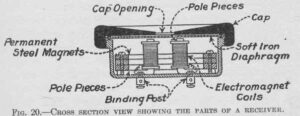
The headphone circuit is next. A diaphragm in the earphone, which moves the air to transfer the sound to your ear, can mechanically follow the audio frequency changes in the amplitude of the signal but not the rf signal, which moves too fast, and passes the rf signal on to ground. Some references would have you believe that the radio frequency and audio frequency signals are split apart by the detector – not true; that really takes place in the headphones.
Making an “Oatbox” Radio
Making a crystal radio is very very simple. Consider the classic “oatbox” radio.
You start by winding 52 feet of hookup wire around the outside of an oatmeal box.
Wind forty turns onto the box. I wind the turns onto the box by holding it between my knees and then winding the wire off the spool around the box. Make sure the turns stay snug, side by side. Every five turns, twist an eyelet in the wire — strip off the plastic coating on the eyelets, but don’t cut the wire, then continue winding. It may help to add masking tape as you go to hold the wire in place.
Examples
Any competent jeweler in 1633 can make a headset, the wire for the coil is nothing special, the form for the coil does NOT need to be an actual oatmeal box, and you can just make the coil longer or shorter to adjust it to work.
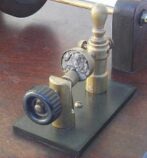
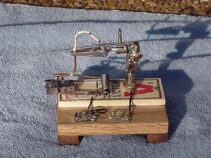
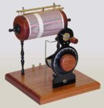
Here are two detectors, one from the early 1900’s the second a home built detector. Both are built to use a lump of lead ore (galena). Fancy variations are possible, but the reality is that a crystal radio is dirt simple. Don’t be taken aback by the mention of a detector (above). A perfectly good detector can be made from a hunk of lead ore (nothing special, just a hunk of rock… really.) and a sharp wire to poke into the rock until you get a signal.
Of course, you can spend inordinate amounts of time to make ELEGANT crystal radios if you want to. This, for example was the clear winner in the 2001 crystal radio building contest – freestyle – master division. The builder built everything including the air-variable capacitor, the detector, the coils, everything in his home shop. Amazing.
Summary
So, crystal radios are simple to build, work fine, are well within the ability of 17th century technology and will be GREAT for listening to the VOA. The 2002 crystal radio builders challenge contest winner logged 1294 stations with a record distance of over 3000 miles in the course of a month using no batteries, no power of any kind, just a crystal radio, home made headphones, and persistence and care. Which, frankly, is my concern. Other than VOA which we WANT everyone to listen to, I’m not interested in folks listening in to our military and diplomatic communications.
So, I relegate crystal radios and spark transmitters to the French. (And possibly the Chinese.)